E-Paper Calendar V2: Lighting Up the Mainboard
This article is migrated from Medium and translated by Gemini pro 2.5.
This post was also written with the help of GPT.
Changing the Mainboard: The Choice to Move from WROOM to S3
In the early stages of planning the V2 project, I had originally planned to stick with the ESP32-WROOM series as the main controller. However, after further reviewing the requirements and use cases, I decided to upgrade the mainboard to the ESP32-S3-WROOM-1-N16R8 and make it the primary platform for this development.
This wasn’t a random decision; it was a choice made after a round of in-depth research with GPT. I provided my requirements and limitations, and it helped me organize a comparison of the pros and cons of various platforms on the market, including different ESP32 modules, STM32, and Raspberry Pi.
In the end, considering development efficiency, extensibility, cost, and the physical user experience, the ESP32-S3 seemed exceptionally reasonable for this project.
One of the specific deciding factors was the interface: most ESP32-WROOM boards use micro-USB, while the S3 DevKit is upgraded to Type-C. This is a significant improvement for the development phase. Not only do I not have to check the connector orientation, but it’s also more durable for repeated plugging and unplugging, and it provides more stable power delivery. While these details don’t affect the firmware development itself, for a device that requires frequent testing and flashing, it makes a tangible difference in efficiency.
Choosing the ESP32-S3-WROOM-1-N16R8 also means having more ample resources (16MB Flash, 8MB PSRAM). These will be very useful later when I need to support various fonts, custom background images, or pre-load weather icons.
An LED is Not Just an LED
After selecting the development board, I planned to start with the most basic “Blink” test. To verify that the development environment and flashing process were working, I asked GPT to write a simple blink program for me.
But this time, the LED was different. The light on the ESP32-S3 DevKit isn’t a standard indicator light controlled by a simple GPIO. It’s a WS2812 (also known as NeoPixel)—a smart RGB LED that requires a specific data format to be sent via the RMT (Remote Control) peripheral.
I asked GPT to write an ESP-IDF example for the WS2812, and it did provide a well-structured piece of code. But when I actually tried to compile it, I ran into a problem: the program referenced led_strip_encoder.h, which could not be found, causing the build to fail.
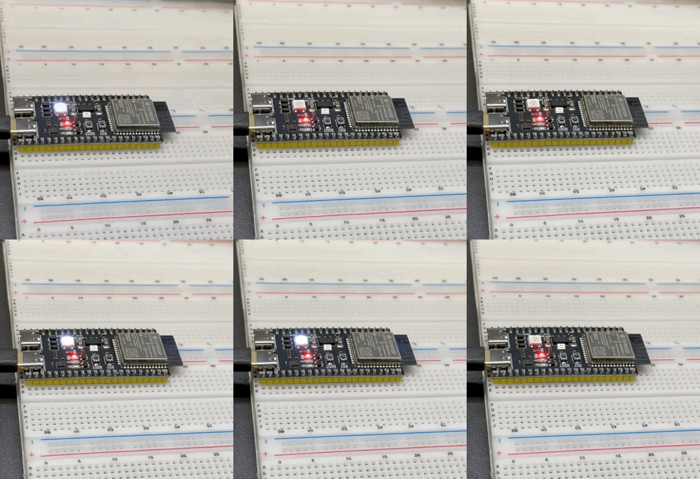
I later discovered that this header is one of the components built into ESP-IDF v5.x and later, and it also requires you to first enable the corresponding component support in menuconfig. Considering the time and for the sake of simplicity, I eventually switched to using the led_strip example built into the ESP-IDF examples directory. After enabling the option in menuconfig, I successfully lit up the WS2812.
The LED lit up in sequence—Red, Green, Blue—which meant the entire compile → flash → run toolchain was working. The development board was also stable in providing power and driving peripherals.
This step is a small milestone in the V2 project, but it’s the critical opening act for getting the whole system working. Next, I will proceed to the more challenging features, such as: ICS calendar parsing, deep-sleep wakeup control, web-based configuration, and screen drawing. Each of these features will run into the limitations I faced in V1, and this time, I plan to solve every single one of them cleanly.
