E-Paper Calendar V2 Hardware: Ultra-Low Power
This article is migrated from Medium and translated by Gemini pro 2.5.
(Article written by Gemini 2.5 Pro, with personal supervision.)
In my last post, we laid out the blueprint for the V2 circuit board, aiming to drastically reduce costs and increase integration without sacrificing the core experience. Before I left for a business trip to the UK, I rushed to submit the SMT order for V2.1.
Just like that, I spent two weeks on my trip, filled with both anticipation and anxiety. As soon as I returned to Taiwan, I was greeted by a fresh batch of new circuit boards and a new toy I bought specifically for this challenge: a hot air gun.
My plan was to save on development costs by using the hot air gun to recover the ESP32-S3 module from the old, functionally-correct-but-power-hungry board.
V2.1 Validation: An Unexpected Power Mystery
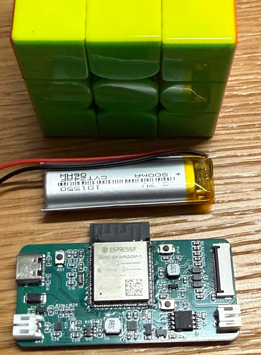
I skillfully removed the ESP32-S3 from the old board with the hot air gun and carefully soldered it onto the new V2.1 board. The V2.1 design included all our planned fixes: the TPS63031’s PS/SYNC pin was grounded, and a MOSFET switch was added for independent peripheral power control.
I confidently flashed the latest test firmware, which cuts power to the SPI Flash and e-paper driver via the power switch before sleeping. Then, I connected my multimeter in series with the battery to measure the sleep current…
800µA
This number baffled me. It didn’t make sense. Based on my last debugging session, after eliminating all peripherals, the hardware baseline power consumption should have been in the tens of micro-amps (µA). Could it be that the TPS63031’s sleep current wasn’t as low as the datasheet claimed? But the difference shouldn’t be this large.
After several repeated tests, I unexpectedly found that one of the other boards in my hand could stably achieve a beautiful 70µA.
Same design, same components, same firmware… why was the power consumption so vastly different? The only variable was the ESP32 module recycled from the old board.
Could it be? When I desoldered it, the high heat was applied for a long time to get it off. Could this have caused some kind of microscopic internal damage to the ESP32?
To verify this theory, I purchased a brand new ESP32-S3 module and soldered it on. Powered it up, flashed, measured… 70µA! The result was stable.
Finally, the mystery was solved: the problem was the recycled ESP32 chip. Although it appeared to function normally, its internal current leakage was abnormally high. This experience taught me that high-temperature desoldering definitely carries a risk of damaging the chip. My wallet hurts a bit from buying a new ESP32, but at least this confirms the V2.1 circuit design is a success and doesn’t need another revision!
Interlude: The Multimeter’s “Range Trap”
During this debugging process, another incident occurred that made me want to give up. Several times, I would clearly see the sleep current stabilize at 70µA, but when I measured it again later, it would jump to 360µA.
This strange phenomenon plagued me for a long time. I later discovered the problem was my multimeter. When the ESP32 is in its active state, the ~100mA current draw forces the multimeter to switch to its high-current mA range. When the ESP32 enters sleep and the current plummets to the µA level, the multimeter’s auto-ranging function doesn’t switch back fast enough. This results in a measurement in the wrong range, causing a massive error in the reading.
When I quickly lifted and re-applied the probes, forcing the meter to re-detect the current range, it would correctly read 70µA again. In the end, I adopted a method of shorting the probes with a wire, waiting for the device to enter sleep, and then removing the short to start measuring. This confirmed it was indeed a range-switching problem with the meter.
Evolving AI Collaboration: Creating Long-Term Memory with GEMINI.md
While solving hardware problems, I was also optimizing my collaboration workflow with AI.
At first, I asked gemini-cli to think of some software-based solutions to optimize sleep current. But lacking full context, the suggestions it gave were ineffective. Finally, gemini-cli even “surrendered,” saying it needed me to provide the complete circuit diagram to give better advice.
This made me realize a problem: every time I start a new gemini-cli conversation, I have to treat it like a new intern, re-explaining what my project is, what the hardware settings are, how the pins are allocated… just to ask my real question. This was too time-consuming.
Fortunately, I discovered that gemini-cli provides a perfect solution: the GEMINI.md file.
This is a context “memory” file. When executed, gemini-cli automatically reads the contents of all GEMINI.md files in the current and parent directories and uses them as background knowledge.
I immediately had Gemini help me organize my V2.1 hardware specs into a GEMINI.md file, and I’ve been updating it throughout my debugging process.
Now, every time I open a new gemini-cli session, it’s like it has long-term memory. It immediately knows my project’s architecture and hardware details. I can get straight to the point, and my questions become much more efficient and precise.
Final Battery Life Estimation
After so many rounds of debugging, we finally have an ideal sleep power consumption number. Now, let’s use this final, real-world data to see the product’s theoretical battery life in different scenarios.
Calculation Parameters:
- Battery Capacity: 800 mAh
- Total Sleep Current: 70µA (0.070 mA)
- Total Active Current: 100 mA
- Update Frequency: Once per day
Battery Life Based on Daily Active Duration:
| Daily Active Duration | Estimated Total Daily Consumption | Estimated 800mAh Battery Life |
|---|---|---|
| 20 Seconds | (0.070mA * 24h) + (100mA * 20/3600h) ≈ 2.24 mAh | ~ 357 Days (Almost a year) |
| 1 Minute | (0.070mA * 24h) + (100mA * 60/3600h) ≈ 3.35 mAh | ~ 239 Days (Almost 8 months) |
| 3 Minutes | (0.070mA * 24h) + (100mA * 180/3600h) ≈ 6.68 mAh | ~ 120 Days (Approx. 4 months) |
Conclusion: This result is incredibly encouraging! Even if we consider a longer active time (e.g., 1 minute, in case of bad Wi-Fi or a large ICS file), 239 days of battery life far exceeds our initial design goal of “recharging once every three months.” This proves the V2.1 hardware power control is a huge success and provides enormous confidence and margin for the software development ahead.
Summary
The V2.1 hardware validation was a roller-coaster, but the final result is thrilling. We successfully controlled the sleep power consumption to under 70µA, and the hardware design is now stable. More importantly, during this debugging process, we not only learned valuable hardware lessons but also optimized our collaboration model with AI.
The hardware foundation is now laid. It’s time to shift our focus back to the software and begin full-scale integration!